PPM Drone Relay Module
Sole designer. A deployable ground relay that extends a commercial drone's control range by 82% — roughly 300 m — by pulling the PPM control signal apart, retransmitting it as data, and rebuilding it at the aircraft.
- Role
- Sole designer
- Organisation
- Independent research (AP Research)
- Dates
- Aug 2024 – Mar 2025
- Status
- Complete
- Tags
- Arduino / C++ · nRF24L01+ · FDM · Oscilloscope bench work
- Range gain
- +82% (≈300 m / 900 ft)
- Added latency
- 0.25–0.5 s at maximum range
- Link
- 2.4 GHz nRF24L01+ transceivers
- Compute
- Arduino Nano, C++
- Airborne package
- Custom FDM capsule under the frame
- Write-up
- 5,000-word research paper, scored 5
Why it exists
Small drones are used in exactly the places where radio links fail: disaster zones, dense terrain, urban rubble, contested ground. The aircraft is capable of flying further than the operator can talk to it, and the limit is the link, not the airframe.
The idea was a relay small and cheap enough to be thrown on a roof, wedged in a tree, or dropped on the ground — a middleman between the pilot and the aircraft that pushes the usable range out far enough to matter for search and rescue.
Requirements
Cheap, using parts a student can buy. The airborne half had to fit in a custom capsule under the drone frame, interface with the stock flight controller, and be light enough that the aircraft still flew normally.
How it works
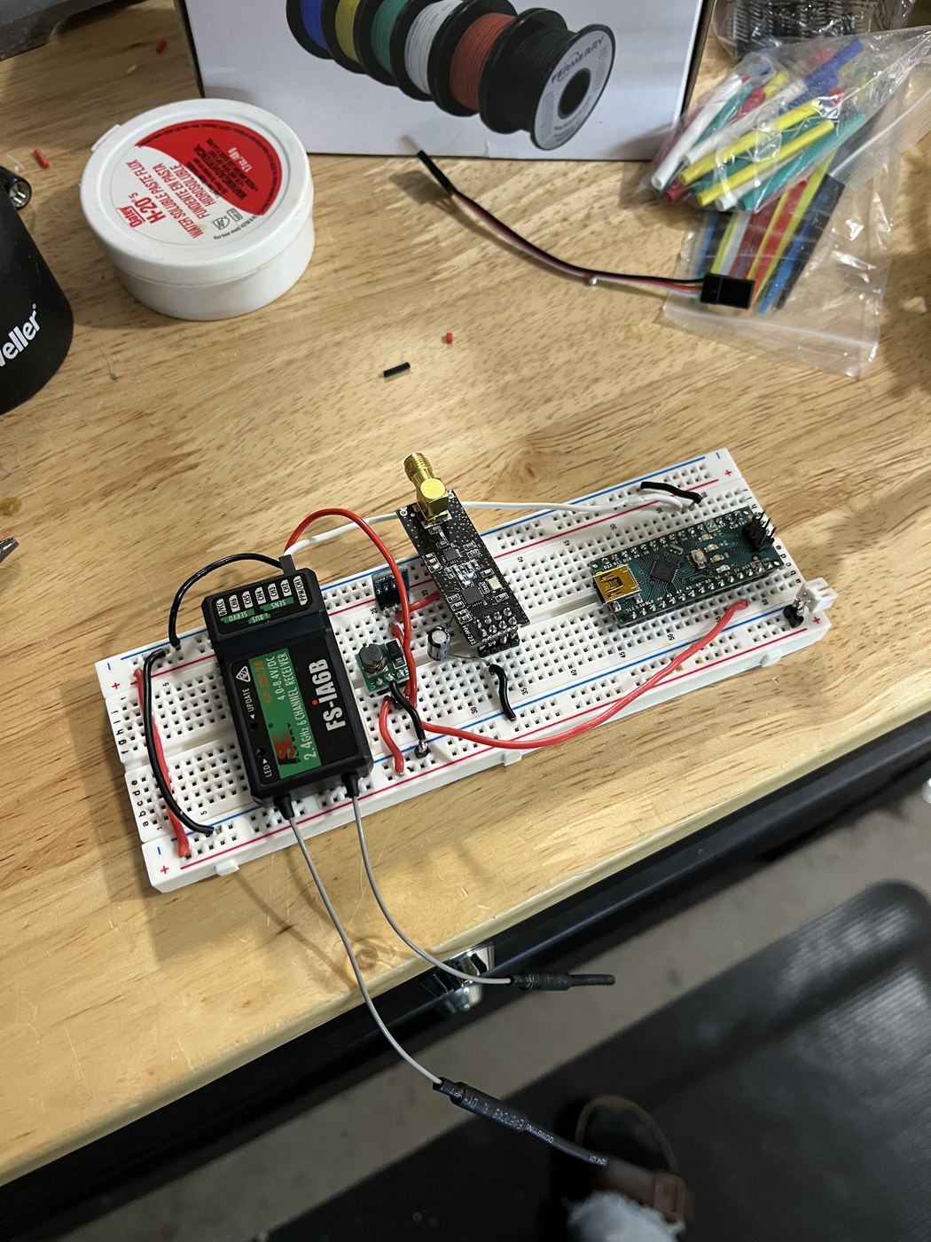
The relay sits between the pilot and the aircraft. It receives the Pulse-Position Modulation signal from the controller on a stock 2.4 GHz receiver, and an Arduino Nano decomposes that pulse train into an array of throttle, yaw, roll, and pitch values.
Those values go out over an nRF24L01+ transceiver as data. A second transceiver on the drone hands them to a second Arduino, which reconstructs a valid PPM pulse train and feeds it into the flight controller's PPM input. The flight controller cannot tell the difference between that and the receiver it shipped with.
The airborne electronics live in a custom FDM-printed capsule that mounts below the frame, with the wiring routed out to the flight controller.
Key decisions
Boosting the signal vs. taking it apart
- Off-the-shelf RF repeaters — large, expensive, and not portable enough to deploy in the field
- Intercepting a commercial drone's proprietary link — closed protocol, not realistically attackable
- Decompose PPM into control values, send those as data, rebuild PPM at the aircraft
A DIY drone kit on a plain 2.4 GHz link, and a decompose / retransmit / reconstruct architecture.
Amplifying and rebroadcasting a PPM signal directly means buying hardware that is bigger and more expensive than the drone. Going backwards from the pulse train to the four values it encodes, moving those as a small data packet, and regenerating the pulse train at the far end lets the whole relay run on Arduino Nanos and cheap transceivers. Choosing a kit with an open 2.4 GHz link — rather than fighting a proprietary one — was what made the intercept possible at all.
Packaging the airborne half
- A custom PCB — clean, but slow to iterate on and expensive to respin
- Protoboard
- A breadboard laid out to a rectangular form factor
A rectangular breadboard layout inside a purpose-designed printed capsule.
The circuit changed constantly through testing, so anything I could not rewire in a minute would have cost more time than it saved. Designing the capsule around a known rectangular footprint meant the enclosure could be finished early, with the wiring exit routed to reach the flight controller without fouling the props or shifting the centre of gravity.
Analysis and validation
No simulation work on this one. Validation was done on an oscilloscope: every stage of the chain was probed to confirm the signal was what I believed it was — the controller's PPM output, the decomposed values, and the reconstructed pulse train at the flight controller input.
What went wrong
The whole system worked and the drone would not move.
The scope said the reconstructed PPM was correct: right pulse count, right timing, right frame rate. Nothing in the code or the wiring was obviously wrong, and every subsystem passed on its own. The failure could plausibly have been mechanical, electrical, or software, which is the worst kind.
I went back to what I knew worked. I disconnected my hardware, returned the drone to stock, confirmed it flew, and captured the stock receiver's PPM output on the scope. Comparing that trace against mine, the shape and timing matched — but the stock signal's amplitude was about 3.5× mine. The flight controller was seeing my pulses as noise below its logic threshold.
Scaling the output up by that factor in firmware fixed it on the first test flight. It is the fix I am most pleased with on this project, because finding it required treating three different domains as suspects and ruling them out one at a time rather than guessing.
Result
After iteration, the relay gave a reliable 82% increase in operational range over the stock system — approximately 300 m (900 ft) of additional range — at a cost of 0.25–0.5 s of added latency at the far end of that range, which was noticeable but flyable.
The build, method, and results are documented in a 5,000-word research paper, which scored a 5 on the AP Research exam.
This project has no PI, no NDA, and no export control on it. It is the one thing on this site that can go on GitHub today, and a public repo is the cheapest credibility available. Push the Arduino source, add a README with the architecture diagram, and link it here.