Suspension Compliance Test Jig
Design and CAD lead on a two-person team. The team's first compliance jig: applies 1,000+ lbf to one corner of the car to measure toe and camber compliance and check the suspension model against real numbers.
- Role
- Design and CAD lead
- Organisation
- Bruin Formula Racing — Suspension
- Dates
- Sept 2025 – present
- Status
- In manufacturing
- Tags
- SolidWorks · Haas CNC · Fusion 360 CAM · Waterjet · FEA (planned)
- Applied load
- 1,000+ lbf
- Actuator
- Bottle jack, 4–10 ton capacity
- Measures
- Toe and camber compliance under load
- Axes
- Lateral, vertical, longitudinal
- Instrumentation
- Pancake load cell in series, dial indicators
- Team
- Two members — I led design and CAD
Why it exists
Bruin Formula Racing leans on simulation for suspension design, and until now there was no way to check it. Nobody on the team could say how much the tie rods and A-arms actually deflect under load, which means nobody could say how far the model was from the car.
A teammate and I were given the job of building the team's first compliance jig: something that loads one corner of the car hard enough to produce measurable deflection, so simulated compliance can be compared against measured compliance and A-arm designs can be compared against each other on data rather than on preference.
Requirements
Apply 1,000+ lbf without hydraulics or lab equipment we do not have consistent access to. Buildable in-house. Compact enough to live in the shop. Able to load several points on the suspension so toe, camber, lateral and vertical compliance can all be measured with one piece of hardware.
My role
I designed the jig and did all of the CAD. My teammate led manufacturing. In practice both of us are on the machines — this project is where I learned the Haas mills, Fusion 360 CAM, and the waterjet.
How it works
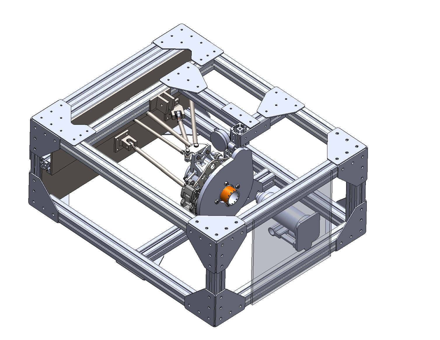
One corner of the car — upright, hub, A-arms, tie rod, pull rod — is mounted inside a fully enclosed t-slot aluminium frame on custom machined plates and mounts that reproduce the chassis pickup points.
A bottle jack sits inside that frame and pushes against it, so the load path closes within the jig. It can be repositioned to load different points on the suspension, which means one jack covers the lateral, vertical and longitudinal cases instead of three actuators.
Force is read by a pancake load cell in series between the jack and the application pad, so the number does not depend on jack pressure or ram friction. Deflection is read with dial indicators at the measurement points, giving compliance directly as movement per unit load.
Key decisions
Where to react the load
- Bolt the corner to a shop bench and push against the bench
- React into a wall or structural corner of the shop
- A purpose-built t-slot enclosure that contains both the suspension and the jack
The enclosed t-slot frame.
Both external options struggled with the same problem — there was no clean way to get 1,000 lbf into the right place without loading something that was never designed to take it. Closing the load path inside the frame makes the jig self-contained and portable, and t-slot extrusion means the jack, load cell and dial indicator mounts can all be repositioned without redesigning the structure.
How to apply 1,000+ lbf
- A hydraulic cylinder and power unit — expensive, plumbing, control complexity
- An Instron or similar test frame — no consistent access, and the corner has to come to the machine
- A bottle jack
A single repositionable bottle jack.
A bottle jack gives 4–10 tons from a compact, cheap, self-contained unit — far more than the 1,000 lbf target, which means the jig is not working near its limit. Because measurement comes from the load cell rather than from the actuator, giving up the fine control of a proper test frame costs accuracy in how the load is applied, not in how it is read.
Analysis and validation
FEA is the next task on this project: the frame and the machined mounts need to be checked at full load, since anything that deflects in the jig shows up as compliance that belongs to the fixture rather than to the suspension. That is the error the whole measurement is sensitive to.
What went wrong
Almost all of the delay on this project has been manufacturing rather than design. The plates and mounts are being cut on the Haas mills and the waterjet, and machine reliability plus shop queue times have set the schedule back repeatedly.
The design lesson is that the part count and the machining time were not treated as constraints early enough — a design that is straightforward to model is not automatically a design you can get through a shared shop before the season needs it.
Frame dimensions, plate thicknesses and material, load cell range, dial indicator resolution, part count, machining hours. Then the payoff: once there is data, what did it show, and did it move the team toward one A-arm geometry or material? Lead the page with that when it exists.
Making it
The plates and mounts are cut from aluminium on the Haas mills and the OMAX waterjet, with stock broken down on the horizontal bandsaw first. I programmed the toolpaths in Fusion 360 CAM — 2D adaptive clearing for the pockets, contour passes for the profiles, and a separate setup for the drilling.
This is the project where I learned all of it: the mills, CAM, the waterjet, and TIG welding. Both of us on the team ended up on the machines regardless of who owned which half of the job.
Where it stands
Machining is in progress. Next is finishing the parts, assembling the jig, running FEA on the frame, and then the first compliance runs.